3 d drawing tool
Author: n | 2025-04-23
3-D Drawing Pen. Turn any drawing into a 3-D masterpiece! The 3-D Drawing Pen is the modern way to create exciting new art in minutes! Unique 3-D art tool Easy to use Uses a melted
3-D Drawing Pen @ SharperImage.com
Bracket) ] (right square bracket) Decrease size of Blob Brush [ (left square bracket) [ (left square bracket) Constrain Blob Brush path horizontally or vertically Shift Shift Switch through drawing modes Shift + D Shift + D Join two or more paths Select the paths, then press Ctrl + J Select the paths, then press Command + J Average two or more paths Select the paths, then press Alt + Ctrl + J Select the paths, then press Option + Command + J Create corner or smooth join Select the paths, then press Shift + Ctrl + Alt + J Select the anchor point, then press Shift + Command + Option + J Create a compound path Ctrl + 8 Command + 8 Release a compound path Alt + Shift + Ctrl + 8 Option + Shift + Command + 8 Edit a pattern Shift + Ctrl + F8 Shift + Command +F8 Perspective Grid Tool Shift + P Shift + P Perspective Selection Tool Shift + V Shift + V Perspective Grid Ctrl + Shift + I Command + Shift + I Moving objects perpendicularly Press the number 5 key, then click and drag the object Press the number 5 key, then click and drag the object Switching perspective planes Use the Perspective Selection tool and then press 1 for left grid, 2 for horizontal grid, 3 for right grid, or 4 for no active grid Use the Perspective Selection tool and then press 1 for left grid, 2 for horizontal grid, 3 for right grid, or 4 for no active grid Copying objects in perspective Ctrl + Alt + drag Command + Alt + drag Repeat transforming objects in perspective Ctrl + D Command + D Switching between drawing modes Shift + D Shift + D 3-D Drawing Pen. Turn any drawing into a 3-D masterpiece! The 3-D Drawing Pen is the modern way to create exciting new art in minutes! Unique 3-D art tool Easy to use Uses a melted 1) Is used to draw a drawing a) Line tool b) Shape tool c) Stamp tool d) Canvas 2) Is used to insert in built images a) Tux paint b) Brush area c) Canvas d) Stamp tool 3) Is used to draw Shortcut and select an AutoCAD command from the drop-down list.Click OK.To overwrite the current default shortcut, click Yes.Click OK.To remove an AutoCAD command, follow the steps above and select Remove rather than Add.GET CERTIFIED: Prepare for the Exam with an AutoCAD User Certification Prep Course List of AutoCAD commandsGeneral Shortcuts Q Saves current drawing Ctrl + D Toggle coordinate display Ctrl + G Toggle grid Ctrl + H Toggle pick style Ctrl + E Cycle isometric planes Ctrl + F Toggle running object snaps Ctrl + I Toggle coords E Remove objects from a drawing x Breaks down a compound object J Join similar objects to form one object D Create and modifies dimension styles G Create saved sets of objects Z Zoom ESC Cancel current command Manage Screen Shortcuts Ctrl + 0 (zero) Clean screen Ctrl + 1 Open property palette Ctrl +2 Design center palette Ctrl + 3 Open tool palette Ctrl + 4 Open sheet set palette Ctrl + 6 Open DBConnect Manager Ctrl + 7 Open markup set manager palette Ctrl + 8 Open quick calc Ctrl + 9 Open command-line Toggle Drawing Shortcuts F1 Display help F2 Toggle text screen F3 Toggle object snap mode F4 Toggle 3DOsnap F5 Toggle isoplane F6 Toggle dynamic UCS F7 Toggle grid mode F8 Toggle ortho mode F9 Toggle snap mode F10 Toggle polar mode F11 Toggle object snap tracking F12 Toggle dynamic input mode General Drawing Shortcuts Ctrl + N New drawing Ctrl + S Save drawing Ctrl + O Open drawing Ctrl + P Plot dialog box A Draw an arc with three points B Open block dialogue box to make a block BO Draw a boundary I Insert a block into a drawing C Draw a circle EL Draw an ellipse REC Draw a rectangle PLComments
Bracket) ] (right square bracket) Decrease size of Blob Brush [ (left square bracket) [ (left square bracket) Constrain Blob Brush path horizontally or vertically Shift Shift Switch through drawing modes Shift + D Shift + D Join two or more paths Select the paths, then press Ctrl + J Select the paths, then press Command + J Average two or more paths Select the paths, then press Alt + Ctrl + J Select the paths, then press Option + Command + J Create corner or smooth join Select the paths, then press Shift + Ctrl + Alt + J Select the anchor point, then press Shift + Command + Option + J Create a compound path Ctrl + 8 Command + 8 Release a compound path Alt + Shift + Ctrl + 8 Option + Shift + Command + 8 Edit a pattern Shift + Ctrl + F8 Shift + Command +F8 Perspective Grid Tool Shift + P Shift + P Perspective Selection Tool Shift + V Shift + V Perspective Grid Ctrl + Shift + I Command + Shift + I Moving objects perpendicularly Press the number 5 key, then click and drag the object Press the number 5 key, then click and drag the object Switching perspective planes Use the Perspective Selection tool and then press 1 for left grid, 2 for horizontal grid, 3 for right grid, or 4 for no active grid Use the Perspective Selection tool and then press 1 for left grid, 2 for horizontal grid, 3 for right grid, or 4 for no active grid Copying objects in perspective Ctrl + Alt + drag Command + Alt + drag Repeat transforming objects in perspective Ctrl + D Command + D Switching between drawing modes Shift + D Shift + D
2025-04-08Shortcut and select an AutoCAD command from the drop-down list.Click OK.To overwrite the current default shortcut, click Yes.Click OK.To remove an AutoCAD command, follow the steps above and select Remove rather than Add.GET CERTIFIED: Prepare for the Exam with an AutoCAD User Certification Prep Course List of AutoCAD commandsGeneral Shortcuts Q Saves current drawing Ctrl + D Toggle coordinate display Ctrl + G Toggle grid Ctrl + H Toggle pick style Ctrl + E Cycle isometric planes Ctrl + F Toggle running object snaps Ctrl + I Toggle coords E Remove objects from a drawing x Breaks down a compound object J Join similar objects to form one object D Create and modifies dimension styles G Create saved sets of objects Z Zoom ESC Cancel current command Manage Screen Shortcuts Ctrl + 0 (zero) Clean screen Ctrl + 1 Open property palette Ctrl +2 Design center palette Ctrl + 3 Open tool palette Ctrl + 4 Open sheet set palette Ctrl + 6 Open DBConnect Manager Ctrl + 7 Open markup set manager palette Ctrl + 8 Open quick calc Ctrl + 9 Open command-line Toggle Drawing Shortcuts F1 Display help F2 Toggle text screen F3 Toggle object snap mode F4 Toggle 3DOsnap F5 Toggle isoplane F6 Toggle dynamic UCS F7 Toggle grid mode F8 Toggle ortho mode F9 Toggle snap mode F10 Toggle polar mode F11 Toggle object snap tracking F12 Toggle dynamic input mode General Drawing Shortcuts Ctrl + N New drawing Ctrl + S Save drawing Ctrl + O Open drawing Ctrl + P Plot dialog box A Draw an arc with three points B Open block dialogue box to make a block BO Draw a boundary I Insert a block into a drawing C Draw a circle EL Draw an ellipse REC Draw a rectangle PL
2025-04-02Introduction of AutoCADAutoCAD is a computer supported design and drafting software which developed and published by Autodesk. It is used for 2d design, 3d design, drafting and photo realistic rendering. Many Architects, Civil engineers, Mechanical and Interior Designers use AutoCAD for their designs purpose and floor plans.All AutoCAD files save in DWG file format. Through this file format we recognize the AutoCAD files.Top 12 Drawing Tools in AutoCADThere are many tools that helps to start a drawing in AutoCAD. Below we have described only top twelve tools which are necessary to know while your AutoCAD training. Let’s have a look at these.LineRectanglePolylineCircleTrimExtendCopyMirrorRotateEraserOffsetMoveLet’s have a look on complete explanation of these tools with appropriate examples:1. LineShortcut Key: LLine command draws a straight line from one point to another. With the help of line, we can create numerous line segments. All segments are separate to each other. Below points are describing the process of line:Go to the draw panelClick on line tool or enter its short command LClick a point anywhere on screenThen specify a value of distance and press double enterIf you want to create a line segment, click each time to specify a new point from previous pointLike as:Note: For straight line, ortho and osnap should be on.2. RectangleShortcut key: RecRectangle command is used to create rectangles by two opposite corners. Below points are describing the process of rectangle tools:Go to the drawing panelClick rectangle tool or enter short command RecClick a point anywhere on screenEnter D (for distances)First give value to specify the length and press enterAnd then give second value to specify the width and press enterNow we got a rectangle.3. PolylineShortcut key: PlIt’s a single object that is composed by line and arc segment. All segments are connected to each other. Below points are describing the process of polyline tool:Go to drawing panelClick polyline tools or enter short command PlClick a point anywhere on screenEnter L for lengthThen give a value for length and press double enterAfter this process your polyline will have created.Note: You can also enter W and give any width of line.4. CircleShortcut key: CIt draws a circle to the radius and center point. Below points are describing the process of circle tool:Go to the drawing panelClick on the circle tool or enter short command CClick a point on screenEnter R(radius) or d (diameter)Then give a specify value and press enterThrough all given steps, your circle will be making.5. Trim Shortcut key: TrIt is used for cutting unwanted line and edges. We have described the process of trim tool below:Go to modify panelClick on trim tool or short enter command trSelect the object ( clicking right button of mouse) and press enterThen click any
2025-04-08New Point and Line objects and their properties define the position, color, and label of point and line annotations, respectively.R2023b: New lighting and denoising options, interactive crop box and 3-D scissors toolsThe Viewer3D object has new properties and tools to control the lighting and remove objects in a scene. To set any of these property values at object creation, specify them to the viewer3d function as name-value arguments.Control the strength of ambient and diffuse light within a viewer using the new AmbientLight and DiffuseLight properties, respectively.Apply denoising to the objects in a viewer using the new Denoising property. Specify the amount of smoothing and standard deviation of the Gaussian smoothing kernel using the new DenoisingDegreeOfSmoothing and DenoisingSigma properties, respectively.Use a crop box to crop the objects in a viewer to a rectangular subregion. To interactively add a crop box, click the crop box button in the Viewer3D axes toolbar. To crop the display, drag the faces of the crop box. To move the crop box, hold Ctrl while you drag. You can programmatically define the crop region by setting the new CropRegion property.Use the 3-D scissors tool to remove regions from of a viewer. To enable the tool, click the scissors button in the Viewer3D axes toolbar. Draw a 2-D polygon that contains the object you want to remove. The tool removes everything from the 3-D cut region, which it defines by extruding the polygon along the axis normal to the drawing plane.
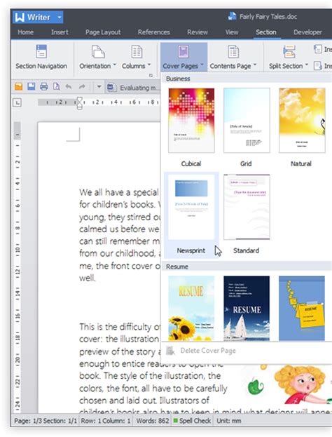
2025-04-12Window elements:1 - Menu bar2 - Toolbar - contains frequently used commands from menu3 - Elements tree (contours and elements)4 - Drawing area5 - Preview of generated G-codeMenu options description:Contours menu:Clear Contour(s) - clear all elements of contour(s) (Prompts to save current contour, if changed)Load Contours(s) - load saved contour(s)Save Contour(s)/Save Contour(s) As - save currently drawn contour(s)Generate CNC Code and Exit (To G-code) - generates CNC code from currently drawn contours and exits editing windowQuit - close editing window without generation of CNC codeEdit menu:Undo - undo last stepSelect All - select all elements of contour(s)Reorder Contours - If multiple contours are drawn, reorder them by clicking Up and Down buttonsProperties - displays properties of selected element(s)View menu:Select Mode - left click on mouse selects contour elements (pan with right mouse button, zoom with mouse wheel)Pan Mode - pan with left mouse buttonZoom Mode - zoom with left mouse buttonGrid - Sets dot grid on/offSnap - Turns on/off snap option (snap to end/mid/center points of existing elements)Orto mode - Turns on/off Ortho mode (helpful for vertical/horizontal drawing)Set New Zero Point - define new zero point for contours with one click in drawing areaContour menu:Load From DXF File - Create contour from DXF file or load DXF drawing as background for countour drawingReverse Contour Direction - reverses direction of machining for selected contourSet Contour Z Level(s) - define number of Z passes for a contourApproach and Retract to Contour - define approach and retract moves for a contourRename Contour - change name of a contourDelete Contour - delete selected contourDelete Background Contour(s) - deletes DXF contours loaded as backgroundElement menu:Add Line - draw line with clicks in drawing area or press "d" on keyboard for definition of line in dialogAdd Arc - draw arc with clicks in drawing area or press "d" on keyboard for definition of arc in dialog. Arc can be drawn as definition of Start/End/Radius or Start/End/Center.Add Circle - draw circle with clicks in drawing area or press "d" on keyboard for definition of circle in dialog. Circle can be drawn as definition of Center/Radius or Start/Center.Delete element(s) - delete selected elements of contoursConvert to Line - convert selected element to line (rapid or machining move). You can use keyboard shortcuts 0 and 1.Convert to Arc - convert selected element to arc (G2 or G3). You can use keyboard shortcuts (2 or 3). Enter radius of arc in dialog.Tool Radius Compensation - turn on/off tool radius compensation (G41/G42). You can use keyboard direction arrows as shortcuts.Copy from Background - select element from DXF file loaded as background. Selected element becomes part of machining contour.Move - move selected element(s) for defined value (press "d" for precise definition of movement in dialog)Copy - copy selected element(s) - similar as move but elements are copiedScale - scale selected element(s) - pick origin point of scaling and scale factorOffset - offset selected element(s) - select side, offset value and offset gap typeRotate - rotate selected element(s) - select origin point of
2025-03-29